A reactive power compensation panel for a furniture store. An automatic controller measures the power factor continuously and switches the compensation steps in and out, keeping the installation within the supplier's limits without manual intervention.
What the panel contains
- Four-pole main switch-disconnector at the incomer, to isolate the whole panel from a single point.
- Fuse protection on every step, mounted on the busbar, so a fault on one step does not affect the rest of the panel.
- Capacitor-duty contactors, one per step, switched by the controller.
- 7 three-phase capacitor steps, to compensate inductive load.
- A three-phase reactor, to compensate capacitive load.
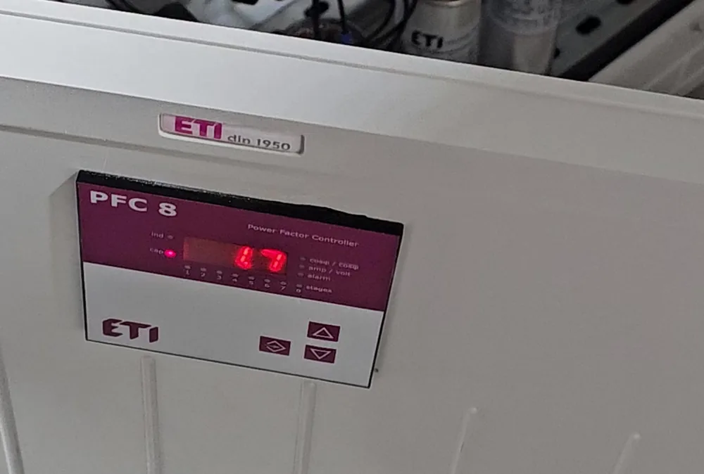
- An 8-step automatic power factor controller, mounted on the panel door, with a display for reading values directly.
Why compensate in both directions
In a commercial building the load is never constant. Motor-driven equipment — air conditioning, ventilation, refrigeration — draws inductive reactive power. LED lighting and electronic equipment, through their switch-mode power supplies, can make the installation capacitive, especially outside opening hours when the inductive load drops. Both conditions are billed separately by the supplier.
That is why the panel combines capacitor steps with a three-phase reactor, and the controller chooses, at any moment, the combination needed to keep the power factor within limits.
Build
The controller's control wiring is routed separately from the power circuits, and each step is wired independently, from its protection to its contactor and capacitor. A faulty step can be taken out of service and replaced without stopping compensation on the others.
For sizing principles and assessment criteria, see our article Power factor correction: sizing and assessment criteria.
Services used in this project
Got a similar job?
We work across residential, commercial and industrial installations. Tell us what you need doing and we will come back with a clear estimate.